Simulation Software for Engineering: Complete Guide
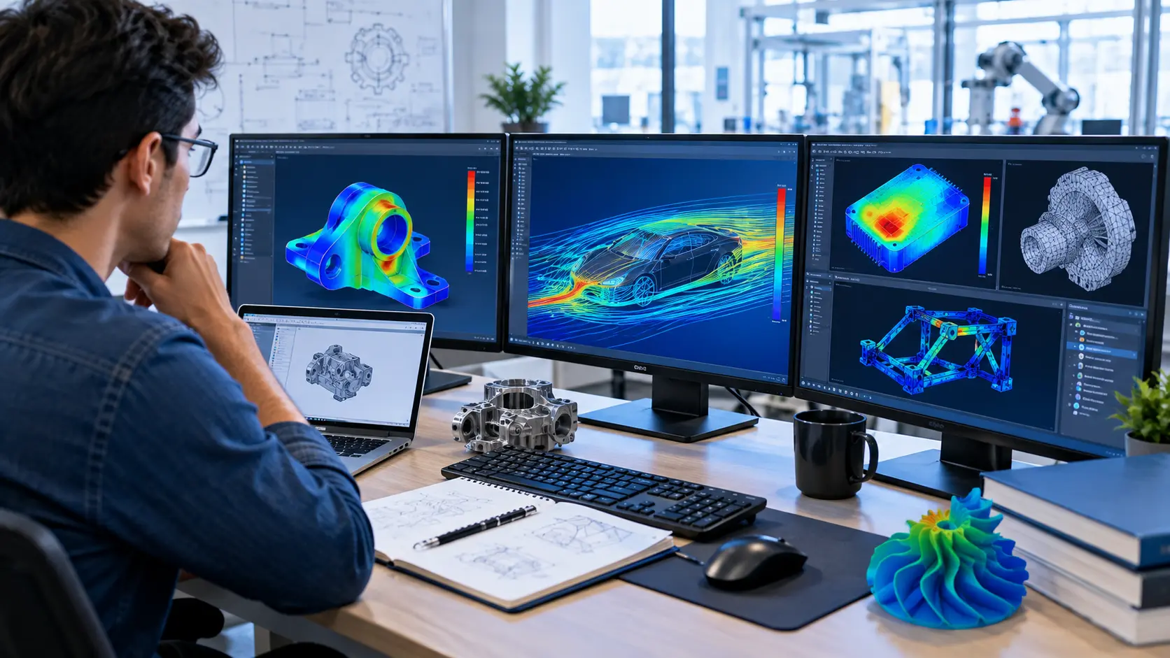
Simulation software for engineering helps engineers test designs, predict how systems may behave, and find potential problems before building physical prototypes. Depending on the engineering field, simulation can cover structural stress, fluid flow, heat transfer, electromagnetics, motion, electronics, and complete system behaviour.
Popular engineering simulation platforms include Ansys, COMSOL Multiphysics, Siemens Simcenter, Autodesk simulation tools, and MATLAB Simulink. The right choice depends on what you need to simulate, your engineering discipline, model complexity, available hardware, and budget.
What Is Simulation Software for Engineering?
Engineering simulation software uses mathematical models and numerical methods to represent how a real product, component, process, or system behaves under specific conditions.
Instead of immediately building and testing a physical design, an engineer can create a virtual model and study different scenarios.
For example, simulation can help answer questions such as:
- Will a component withstand a particular load?
- How will heat move through a product?
- How will air or liquid flow through a system?
- How will a machine respond to vibration?
- How will an electrical or electronic system behave?
- How will different design changes affect performance?
Simulation does not replace engineering judgement or physical testing. Instead, it provides another way to investigate a design and identify issues earlier in the development process. Autodesk describes engineering simulation as a way to analyse and predict product or system behaviour during development, before physical testing and prototyping.
Main Types of Engineering Simulation
There is no single type of engineering simulation. Different problems require different methods.
Finite Element Analysis (FEA)
FEA is widely used for structural and mechanical engineering problems.
An engineer can use FEA to study:
- Stress
- Strain
- Deformation
- Vibration
- Structural loads
- Thermal effects
- Mechanical behaviour
A typical FEA workflow involves creating or importing geometry, generating a mesh, defining materials and boundary conditions, solving the model, and analysing the results.
FEA can be useful when designing brackets, frames, machine components, enclosures, structures, and other products.
Computational Fluid Dynamics (CFD)
CFD is used to study the movement and behaviour of fluids such as air and liquids.
Typical applications include:
- Airflow
- Water flow
- Cooling systems
- HVAC
- Aerodynamics
- Pressure distribution
- Heat transfer
- Electronics cooling
CFD can help engineers explore how a design behaves before building a physical prototype.
Siemens’ Simcenter portfolio, for example, includes CFD capabilities for fluid flow and heat-transfer analysis.
Thermal Simulation
Thermal simulation focuses on temperature and heat transfer.
Engineers may use it to study:
- Temperature distribution
- Heat conduction
- Cooling
- Heating
- Thermal stress
- Electronics thermal management
Thermal analysis can be particularly useful when a product generates significant heat or must operate within a specific temperature range.
Multiphysics Simulation
Some engineering problems involve several physical effects at the same time.
For example, an electronic device may involve:
Electrical behaviour → heat generation → temperature changes → mechanical effects
Multiphysics software allows engineers to combine different physics in one model.
COMSOL Multiphysics is designed for coupled multiphysics as well as single-physics modelling, with capabilities covering areas such as structural mechanics, electromagnetics, acoustics, fluid flow, heat transfer, and chemical engineering.
System Simulation
System simulation focuses on how components work together rather than analysing only one physical part.
This can be useful for:
- Automotive systems
- Robotics
- Aerospace systems
- Control systems
- Embedded systems
- Industrial equipment
- Energy systems
MATLAB Simulink, for example, provides a block-diagram environment for multidomain simulation and model-based design, including system-level simulation and verification.
Popular Simulation Software for Engineering
Different software packages are designed for different workflows. Here are several widely used options.
| Software | Main Strength | Useful For |
|---|---|---|
| Ansys | Broad engineering simulation | FEA, CFD, multiphysics |
| COMSOL Multiphysics | Multiphysics modelling | Coupled physics problems |
| Siemens Simcenter | Integrated simulation and testing | Mechanical, CFD, systems, electromagnetics |
| Autodesk Simulation | CAD-connected design analysis | FEA, CFD, manufacturing |
| MATLAB Simulink | System and dynamic modelling | Controls, embedded and system simulation |
These products are not direct substitutes in every situation. Their capabilities, workflows, licensing models, and learning requirements differ.
Ansys
Ansys provides a broad range of engineering simulation technologies.
Its Workbench environment brings together simulation workflows, while its portfolio includes tools for structural analysis and fluid simulation, among other areas.
Ansys can therefore be relevant for engineers working on complex mechanical, structural, fluid, and multiphysics problems.
COMSOL Multiphysics
COMSOL is focused heavily on multiphysics modelling.
Its platform provides tools for defining geometry, materials, physics, computation, and results analysis. It also supports the creation of simulation applications for other users.
It can be particularly useful when a project combines several physical phenomena.
Siemens Simcenter
Siemens Simcenter covers engineering simulation and testing across multiple disciplines.
Its portfolio includes mechanical simulation, CFD, system simulation, electromagnetic simulation, multidisciplinary design, testing, and related data workflows.
This makes it suitable for organisations that need simulation across different engineering teams and product-development stages.
Autodesk Simulation Tools
Autodesk offers several simulation technologies connected with product design and manufacturing workflows.
Its engineering simulation portfolio includes Autodesk CFD, Inventor Nastran, Moldflow, and Fusion simulation capabilities.
For designers already working within Autodesk’s ecosystem, CAD-connected simulation can provide a convenient workflow.
MATLAB Simulink
MathWorks Simulink takes a different approach from traditional CAD-based FEA or CFD software.
It uses block diagrams to model dynamic systems and supports simulation, system-level design, automatic code generation, and testing of embedded systems.
It is especially relevant to control engineering, embedded systems, automation, and system modelling.
How Engineering Simulation Software Works
Although workflows vary between applications, many engineering simulations follow a similar process.
Define the Engineering Problem
Start with a clear question.
For example:
“Will this aluminium bracket deform too much under the expected load?”
A specific question makes it easier to select the correct simulation method.
Create or Import the Model
The geometry may be created directly inside the simulation software or imported from CAD software.
The model should represent the important features of the real design without adding unnecessary complexity.
Define Materials
Enter appropriate material properties.
Depending on the simulation, these could include properties such as:
- Density
- Elastic properties
- Thermal conductivity
- Specific heat
- Electrical properties
- Fluid properties
Using inappropriate material data can produce misleading results.
Create the Mesh
For many numerical methods, the model is divided into smaller elements or computational cells.
In FEA, this is known as meshing.
The mesh affects both computational requirements and the quality of the numerical solution, so engineers often need to refine it in areas where greater detail is important.
Add Loads and Boundary Conditions
The software needs information about how the model interacts with its environment.
Depending on the problem, this could include:
- Forces
- Pressure
- Temperature
- Constraints
- Motion
- Flow conditions
- Electrical inputs
Incorrect boundary conditions can make an otherwise sophisticated simulation unreliable.
Run the Solver
The solver performs the mathematical calculations needed to obtain the requested results.
Complex models can require significant computing resources.
Some modern simulation platforms support high-performance computing, cloud computing, or GPU acceleration for suitable workloads. COMSOL, for example, currently highlights GPU acceleration and HPC/cloud capabilities in its product suite.
Analyse the Results
The final step is not simply looking at a colourful simulation image.
Engineers need to determine whether the results make physical and engineering sense.
Useful questions include:
- Are the results realistic?
- Are there unexpected concentrations?
- Does the result change significantly with mesh refinement?
- Are the assumptions reasonable?
- Does the simulation agree with available test data?
Why Engineers Use Simulation Software
Simulation can provide several practical benefits.
Reduce Physical Prototyping
Engineers can investigate design variations digitally before manufacturing every physical version.
Autodesk notes that simulation can reduce the need for physical prototypes and destructive testing during product development.
Find Design Problems Earlier
A virtual test can reveal potential weaknesses while a design is still being developed.
This can make it easier to investigate alternatives before production.
Compare Design Options
Engineers can create multiple versions of a design and compare their predicted performance.
For example, they might test different:
- Materials
- Dimensions
- Shapes
- Cooling approaches
- Operating conditions
Explore Difficult Conditions
Simulation can help investigate conditions that are expensive, dangerous, or difficult to reproduce repeatedly in a physical laboratory.
However, simulated extreme conditions still need appropriate modelling assumptions and validation.
How to Choose Simulation Software for Engineering
Choosing software should start with the engineering problem rather than the software brand.
Consider the Physics
First ask what you need to simulate.
If the main problem is structural stress, FEA may be the priority.
If it involves fluid movement, CFD may be more appropriate.
If several physical effects interact, a multiphysics platform may make more sense.
For system-level controls or dynamic behaviour, system simulation tools may be better suited.
Consider CAD Integration
If your engineering team already uses a particular CAD platform, integration can simplify the workflow.
CAD-connected simulation can reduce the need to repeatedly move geometry between separate applications.
Consider Model Complexity
A simple classroom project does not necessarily require an enterprise simulation platform.
Likewise, a complex industrial model may require advanced solvers, automation, HPC support, collaboration tools, and specialised physics.
Consider Learning Requirements
Advanced simulation software can have a steep learning curve.
Look for:
- Tutorials
- Documentation
- Example models
- Training
- Community support
- Technical support
Good documentation can make a significant difference when learning a complex engineering tool.
Consider Hardware and Computing
Simulation can be computationally demanding.
Before selecting software, check:
- CPU requirements
- GPU support
- RAM requirements
- Local versus cloud computing
- HPC support
- Storage requirements
The appropriate setup depends heavily on the size and type of simulations being performed.
Consider Licensing
Engineering simulation software can use different licensing models.
Before purchasing, check the current licensing structure, available modules, user limits, computing options, and educational or trial availability directly with the software provider.
Engineering Simulation vs Physical Testing
Simulation and physical testing serve different purposes.
| Simulation | Physical Testing |
|---|---|
| Takes place in a virtual model | Takes place on a real product or prototype |
| Allows rapid design changes | Tests actual hardware |
| Can explore many scenarios | Provides real-world measurements |
| Depends on assumptions and model quality | Depends on test setup and measurement quality |
| Useful early in design | Useful for validation and verification |
The two approaches are often most useful together.
A simulation can predict behaviour, while physical testing can help validate whether the model represents reality sufficiently well.
Common Mistakes When Using Simulation Software
Powerful software does not automatically produce reliable engineering conclusions.
Avoid these common mistakes.
Using Incorrect Material Data
If the material properties do not represent the actual material or operating conditions, the results may be misleading.
Applying Unrealistic Boundary Conditions
A simulation should represent the real situation as closely as practical.
Incorrect constraints or loads can completely change the result.
Ignoring Mesh Quality
A coarse or poorly designed mesh may fail to capture important behaviour.
Engineers should check whether the solution is sensitive to mesh changes.
Treating Every Result as Perfect
Simulation results are predictions based on a model.
They should be interpreted within the assumptions, inputs, numerical methods, and validation available.
Focusing Only on Visuals
A dramatic colour plot does not automatically mean a design is unsafe or successful.
Look at the numerical results, engineering limits, assumptions, and context.
A Practical Workflow for Beginners
If you are new to engineering simulation, avoid starting with the most complicated model possible.
Try this workflow:
- Choose a simple engineering problem.
- Learn the basic physics behind it.
- Build a simple model.
- Define realistic materials and conditions.
- Generate a suitable mesh.
- Run the simulation.
- Check the results against hand calculations where possible.
- Change one parameter and run the model again.
- Compare the results.
- Gradually increase the model complexity.
This approach helps you understand why the software produces a particular result rather than simply learning which buttons to press.
Frequently Asked Questions
What is the best simulation software for engineering?
There is no single best option for every engineering problem. FEA, CFD, multiphysics, and system modelling require different capabilities. Ansys, COMSOL, Siemens Simcenter, Autodesk tools, and Simulink address different engineering workflows.
Is engineering simulation software difficult to learn?
Some tools are relatively accessible for simple models, while advanced simulation can require a strong understanding of engineering principles, numerical methods, and the software itself. Starting with small models and tutorials is a practical way to learn.
Can simulation replace physical testing?
No. Simulation can reduce the need for some prototypes and help identify issues earlier, but physical testing remains important for validating real-world behaviour and confirming that assumptions and models are appropriate.
Is FEA the same as engineering simulation?
No. FEA is one type of engineering simulation. Engineering simulation is a broader category that can include FEA, CFD, thermal analysis, electromagnetics, system simulation, motion analysis, and multiphysics modelling.
Can engineering simulation run on a normal computer?
Some small models can run on ordinary engineering workstations, while large simulations may require substantial computing resources. The requirements depend on the solver, model size, mesh, physics, and desired analysis time.
Conclusion
Simulation software for engineering allows engineers to investigate designs and systems before relying entirely on physical prototypes and tests. The right tool depends on the problem. FEA is useful for structural analysis, CFD for fluid and heat-flow problems, multiphysics platforms for coupled physical effects, and system simulation tools for dynamic or control-oriented models. Software such as Ansys, COMSOL Multiphysics, Siemens Simcenter, Autodesk simulation products, and MATLAB Simulink each serve different purposes. Instead of choosing based only on popularity, consider the physics involved, CAD workflow, model complexity, computing requirements, learning resources, and licensing. Most importantly, treat simulation as an engineering tool rather than a replacement for engineering judgement. A well-defined model, realistic inputs, appropriate numerical methods, and sensible validation are just as important as the software itself.